Why bonding resistance is measured
What is bonding resistance, and why do aircraft and fuel systems have to be checked on a schedule?
Electrical bonding uses conductive paths to hold structure, plumbing, equipment cases and the grounding system at one potential. It does three jobs. During a lightning strike it carries tens of thousands of amps along the skin of the aircraft instead of through the fuel tanks or the avionics. Static charge generated by fuel flow and by friction in flight has to keep bleeding off, or it builds up at the filler port or inside the tank until it sparks. Avionics and radio systems need a low impedance EMI return path, and a poor bond turns straight into noise and interference.
Bonding resistance is the health indicator for that path. Corrosion, vibration loosening a joint, repainting and part replacement all raise the resistance of a bond, and none of it is visible from the outside. That is why maintenance manuals call for the bonding resistance to be measured and recorded at set inspection intervals, and again after any work that disturbs a bond. Launch pads, fuel storage tanks and refueling facilities verify their grounding and bonding on a schedule for the same two reasons, static and lightning.
What is a typical bonding resistance limit?
There is no single universal number. The limit comes from the aircraft maintenance manual, the structural repair manual or the facility specification, and even on one aircraft the classes of bond differ: lightning protection, static dissipation, avionics grounding and fuel system bonding all have their own limits. In practice the numbers you meet are in the milliohm class, limits on the order of 2.5 mΩ or 10 mΩ, while static dissipation limits can be as loose as the ohm class.
For the technician the point is not to memorize a number. Look up the class and the limit for that bond in the manual first, then confirm that the range and resolution of the instrument can produce a meaningful pass or fail at that limit. If the limit is 2.5 mΩ, an instrument with 1 mΩ resolution can only tell you "about 2 or 3", and that call will not survive an audit. You need resolution in the 0.01 mΩ class, such as the 0.01 mΩ the 620LK gives on its 200 mΩ range, or the 0.001 mΩ the 620LK-HR gives on its 20 mΩ range.
Method: 4-wire, test current and ranges
Why does milliohm work have to be 4-wire? Will a multimeter not do?
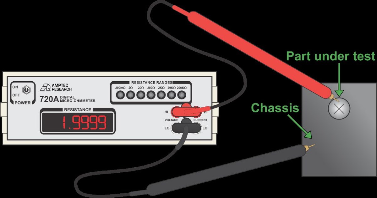
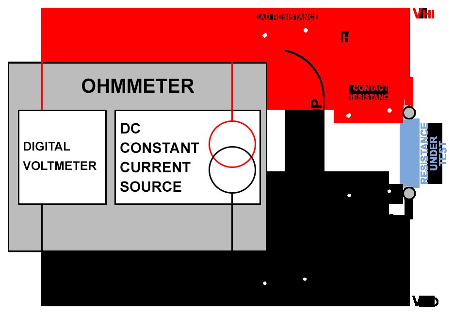
An ordinary multimeter measures with two wires: the same pair carries the test current and senses the voltage, so the resistance of the leads and the contact resistance between clamp and workpiece are both added to the reading. One set of leads plus two clamp points easily comes to tens or hundreds of milliohms, an order of magnitude more than the bond you are trying to measure. In that situation almost all of the reading is lead resistance, not the bond.
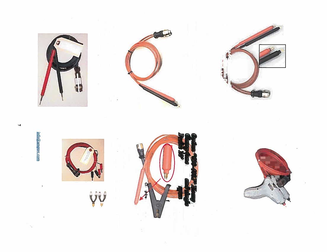
A 4-wire Kelvin connection separates current drive from voltage sensing. One pair carries the 100 mA test current, the other pair only picks up the voltage across the bond and carries almost no current, so lead and contact resistance do not enter the reading. That is why the 620LK, 620UK-B and 620LK-HR are all four wire instruments, with dedicated Trident terminals and 4-wire probes: each probe tip is one current point and one voltage point. Note that if you buy a 4-wire instrument and then hook up ordinary two wire alligator clips, the advantage is gone.
Why do bonding testers have a 200 mΩ and a 2 Ω range? Why is the test current 100 mA?
The two ranges map onto the two layers of bonding work. The 200 mΩ range, resolution 0.01 mΩ, covers lightning protection and primary structural bonds with milliohm class limits. The 2 Ω range, resolution 0.1 mΩ, covers static dissipation, equipment grounding and longer bonding paths. Accuracy on the 620LK and 620UK-B is ±0.05% of reading and range on both ranges.
The nominal 100 mA test current is a compromise between accuracy and safety. To get a stable voltage signal out of a milliohm the current cannot be too small: 100 mA through 1 mΩ produces only 100 µV, already near the limit of what the instrument has to resolve, and a lower current makes the signal to noise ratio worse. The current cannot be raised without limit either, because the instrument has to work where fuel vapor may be present and the available energy must stay bounded. That is why this family runs an open circuit voltage of about 5 VDC, a maximum internal voltage of 6 VDC, and carries UL-913 intrinsic safety certification. If your application needs the lower 20 mΩ range, the 620LK-HR raises the current to 1 A on that range to hold resolution, and drops it to 10 mA on the 20 Ω range.
What does intrinsically safe mean, and why is it mandatory near fuel vapor?
Intrinsic safety is a protection method: the electrical and thermal energy the instrument can release, in normal operation and under any single fault, is limited to a level that cannot ignite the specified class of flammable gas or vapor. UL-913 is the independent certification standard for such instruments. MIL-STD-810 Method 511 is the test performed in an actual explosive atmosphere, proving the instrument can be operated in a fuel laden environment.
Bonding checks are usually done exactly where the risk is highest: around wing tanks, at filler ports, on fuel line flanges, on top of storage tanks, along propellant lines on a launch pad. Fuel vapor can be present in those areas during maintenance, and a bonding measurement by definition drives current into metal structure. With a non certified instrument, an internal capacitor discharging or a probe drawing an arc is an ignition source. The 620LK and 620UK-B carry independent UL-913 certification and meet MIL-STD-810 Method 511F / 810F, the 620LK-P5 is also UL-913 and MIL-STD-810 qualified, and the 620LK-HR is UL-913 compliant. Treat intrinsic safety certification as a mandatory purchasing requirement, not a bonus feature.
Working practice and model selection
How often does bonding resistance have to be verified?
Follow the maintenance manual. Airframe structural bonds are normally tied to the scheduled inspections for that type, and in addition any removal, repainting, fastener replacement or repair of a bond calls for a fresh measurement and record. Grounding and bonding at fuel facilities and launch pads is verified on the schedule in the facility safety specification, with an extra check after a lightning event.
The instrument needs its own calibration interval. AMPTEC instruments ship with an N.I.S.T. traceable calibration certificate. Put the instrument on the measuring equipment list in your quality system and return it for calibration on your internal schedule, commonly annual. We also suggest a self check before each job: read a known resistance, such as a shorting bar or a low resistance standard, to confirm the instrument and the lead set are reading correctly before you touch the workpiece.
What is the difference between the 620LK, 620UK-B, 620LK-HR and 620LK-P5, and how do I choose?
The 620LK is the standard bonding milliohmmeter: 200 mΩ and 2 Ω ranges, resolution 0.01 mΩ and 0.1 mΩ, accuracy ±0.05% of reading and range, 100 mA test current, four AA alkaline cells, 3.2 lbs for the mainframe, operating range -20°C to 50°C, certified to UL-913 and MIL-STD-810 Method 511F. It is the instrument of choice on many commercial airliner and US Air Force programs, and it suits most airframe structural bonding work.
The 620UK-B has the same ranges, resolution, accuracy, test current, power source and weight as the 620LK (200 mΩ and 2 Ω, 0.01 mΩ, ±0.05%, 100 mA, four AA cells, 3.2 lbs) and the same UL-913 and MIL-STD-810F certification. The difference is the US military NSN 6625-01-542-7487. It is widely used by US Air Force maintenance units, so if your procurement or maintenance system works from NSNs, take the 620UK-B.
The 620LK-HR is the high resolution version. Below the two 620LK ranges it adds a 20 mΩ range with 0.001 mΩ resolution and 1 A test current, and above them a 20 Ω range with 1 mΩ resolution and 10 mA test current. Accuracy is ±0.025% of range across all four ranges, it runs on an internal rechargeable battery pack and weighs 3 lbs. It suits units with unusually tight limits, or those who want one instrument covering both milliohm and ohm class bonds. It was originally designed for Lockheed Martin.
The 620LK-P5 sits somewhere else. It is a ground continuity tester with 20 Ω and 200 Ω ranges, resolution 0.001 ohm and 0.01 ohm, accuracy ±0.05% of range, and a test current of only 1 mA or 0.1 mA. It is not for milliohm class structural bonds. It uses low current to confirm safely that continuity between equipment, harnesses and ground is inside an ohm class limit, which suits safety sensitive grounding checks and production line work. It ships with the 630-100 carrying case and a 10 foot lead set.
The short version: take the 620LK for structural bonds and lightning protection points, or the 620UK-B if you need the NSN; take the 620LK-HR if the limit is low enough to need 0.001 mΩ or the range has to reach 20 Ω; take the 620LK-P5 for ohm class ground continuity and low current requirements.
What are the most common mistakes in a bonding measurement?
First, the probe never reaches bare metal. Anodizing, paint, oxide film and sealant are all insulators, so the probe has to contact bare metal or the designated bonding test point, otherwise you are measuring the coating instead of the bond. Second, using the wrong range, or misreading the "1 reading per 3 seconds" update rate: this family updates the reading every 3 seconds, so hold the probes on and wait for the reading to settle rather than recording the first number that appears. Third, ignoring temperature. Bond resistance changes with temperature and the instrument has a temperature coefficient of its own (±0.0025% per 1 C on the 620LK and 620UK-B), so noting the ambient temperature helps when you are working hot or cold outdoors and reading a marginal value. Fourth, the lead set. Worn leads and oxidized clamp points degrade the 4-wire measurement, so calibrate the lead set together with the instrument.