
Why an ordinary multimeter can set off an igniter
Igniters, squibs, electric detonators and exploding bridgewires (EBW) all rely on a thin bridgewire to convert electrical energy into heat or shock and start the device. The bridgewire itself is nothing more than a resistance of a few tens of milliohms to a few ohms, and measuring a resistance sounds like the most basic task there is. The problem is that measuring resistance necessarily means sending current through the bridgewire, and current through the bridgewire is exactly how the device is meant to work.
The data sheet of every electro-explosive device defines a no-fire current, below which continuous application is guaranteed not to initiate, and an all-fire current, above which initiation is guaranteed. Both numbers vary by device, and a sensitive device may have a no-fire value of only a few tens of milliamps. The ohms range of a general purpose digital multimeter is not designed for this: its test current changes with the range, the specification usually does not guarantee an upper bound, and there is no mechanism at all to hold the current down when an internal component fails. In other words, you do not know how much current it is delivering right now, and you do not know how much it will deliver when it breaks. For a sensitive explosive device that is an unacceptable risk.
The difference between a safety ohmmeter and an ordinary ohmmeter is therefore not accuracy but design philosophy. The safety ohmmeter treats never exceeding a given current as the first priority, and achieves its accuracy within that constraint.
What failsafe current limiting and 4-wire Kelvin measurement mean
A failsafe current limit means that under any single fault condition, including a shorted internal transistor, the wrong range selected or an abnormal battery voltage, the current the instrument delivers into the device under test cannot exceed a guaranteed value. On the AMPTEC 620A-4 the specification states a failsafe maximum current of 8 mA that is not exceeded under any fault condition. The 620UK-V4 likewise has a failsafe current of 8 mA on the 2 Ω to 20 Ω ranges, falling on higher ranges in steps to 1.5 mA, 150 µA and eventually 15 nA. The open circuit voltage is held low as well (below 1.4 V on the 620UK-V4, 1.6 VDC on the 620A-4), so that not even the moment of contact can deliver enough energy to initiate. That is a different concept from the nominal test current, which is the value the instrument delivers in normal measurement (5 mA on the low ranges of the 620UK-V4); the failsafe current is the worst case ceiling.
The 4-wire Kelvin connection is what delivers the accuracy. Bridgewire resistance is often around 1 Ω, while the contact resistance of test leads and fixtures easily reaches tens to hundreds of milliohms. With a 2-wire measurement that lead resistance is added straight into the reading and the error can be larger than the bridgewire itself. A 4-wire connection separates sourcing current from sensing voltage onto two independent pairs: the current pair carries the test current, the voltage pair senses only across the bridgewire and carries almost no current, so lead and contact resistance do not enter the reading. That is how the 620A-4 achieves 1 mΩ resolution on the 20 Ω range with ±0.02% of reading and range accuracy across all ranges. Without the 4-wire architecture, that specification would mean nothing in the field.
Check both items when selecting: whether the guaranteed failsafe current is below the no-fire current of every device you will test, with margin left over, and whether the measurement terminals are 4-wire Kelvin. An instrument missing either one is not a qualified igniter tester.
What UL-913, ATEX and MIL-STD-810 each stand for
These three terms are usually listed together on a data sheet, but they prove different things and a buyer should read them separately.
UL-913 is the UL standard in the United States for certifying intrinsically safe instruments. Its core requirement is that the electrical and thermal energy the instrument can release, in normal operation and under fault, stays too low to ignite the specified class of flammable gas or vapor. An instrument with independent UL-913 certification has had its energy limiting design verified by a third party rather than merely asserted by the manufacturer. The AMPTEC 620A-4, 620UK-V4, 720A and 601ES all carry UL-913.
ATEX is the EU directive for equipment used in explosive atmospheres. The 620UK-V4 is marked as complying with the EU ATEX directive and the intrinsic safety standard Eex-9b-IIc-T4. If your project has European customers, or the equipment moves in and out of controlled sites in the EU, this item becomes a requirement rather than a bonus.
MIL-STD-810 is the US military environmental test standard, and its Method 511 is the explosive atmosphere test, which proves an instrument can be operated in an atmosphere full of fuel vapor without igniting it. The 620A-4 is certified to Mil. Std. 810 Method 511 and can be used in a fuel-laden environment; the 720A and 601ES also list MIL-STD-810-511. This complements UL-913: one looks at circuit energy, the other at behavior in a real explosive atmosphere.
Two further kinds of approval are worth noting: US Air Force Nonnuclear Munitions Safety Board approval (620A-4, 720A) and NASA range safety approval (720A, 601ES). These are not certification standards but permissions granted by particular using organizations, and for defense and aerospace projects in Taiwan they indicate that the instrument already has a service record in the corresponding environment.
A decision path: start with where you measure and what you measure
First question: are you measuring an explosive device or an ordinary low resistance? If the item under test is an igniter, squib, detonator, flare or bridgewire, take the safety ohmmeter route. If it is bonding resistance, a transformer winding, a contact or a component resistance, what you need is a micro-ohmmeter, and there is no reason to pay for current limiting with reduced range coverage.
Second question: where do you measure? A laboratory or an ordnance inspection station has a stable bench and mains power and suits a bench-top instrument. An aircraft ramp, a magazine or a field preparation line needs a portable, battery-powered unit. Field exercises or an offshore platform call for a ruggedized model that survives drops, rain and temperature extremes.
Third question: what is the lowest range and resolution you need? Bridgewires usually sit around 1 Ω, so a 20 Ω range with 1 mΩ resolution is already sufficient. If you also have to check leads and insulation at the kΩ level, you need a model that extends to 20 kΩ or even 2 MΩ.
Last question: before you connect to the device under test, could there be voltage on the circuit that should not be there? On ranges, launch pads and preparation areas, confirming that the circuit is free of stray voltage before measuring resistance is standard practice, and it calls for a different class of instrument, the safety multimeter.
Model comparison: 620A-4, 620UK-V4, ruggedized units, 720A and 601ES
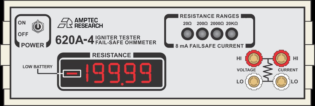
Precision bench-top unit: the 620A-4. This is the flagship AMPTEC igniter circuit tester, with 20 Ω / 200 Ω / 2 kΩ / 20 kΩ ranges, ±0.02% of reading and range accuracy on all ranges, 1 mΩ resolution on the 20 Ω range, a failsafe maximum current of 8 mA and an open circuit voltage of 1.6 VDC. It has a 4½ digit LED display updating 3 times per second, a temperature coefficient of ±0.002%/°C, a weight of 3.5 lbs, and it is powered by four rechargeable 5 AHr NICAD cells. It suits ordnance inspection, laboratory acceptance testing and any measurement that demands the best repeatability. It is approved by the US Air Force Nonnuclear Munitions Safety Board and certified to MIL-STD-810 Method 511.
Portable field unit: the 620UK-V4. A portable EEX digital safety ohmmeter with seven ranges from 2.0 Ω to 2.0 MΩ, ±0.02% of reading accuracy on the best range, a failsafe maximum current of 8 mA, an open circuit voltage below 1.4 V, 4-wire Kelvin terminals and a 4½ digit LCD. It complies with ATEX and Eex-9b-IIc-T4 and passes MIL-STD-810. It runs on 1.5 V alkaline cells, measures 7" × 8" × 3" and weighs 8 lbs. Its range coverage is far wider than that of the 620A-4 and, with the European certification, it suits field work and international projects that have to cover bridgewire, lead and insulation type checks with one instrument.
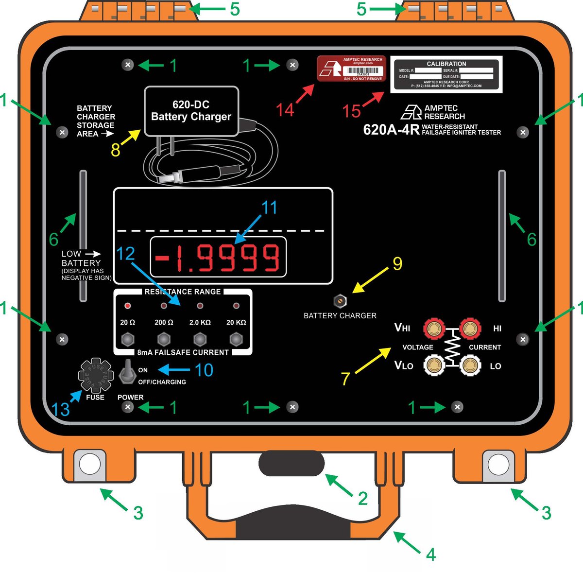
Ruggedized field units: the 630 and 640 families (630BN, 630ES, 640N, 641N, 641RS, and the ruggedized 620A-4R version of the 620A-4). This group keeps the same intrinsically safe and failsafe design but puts the emphasis on enclosure protection, drop resistance and built-in self test, and it is built for demanding field environments. If your work happens on a training range, aboard ship or on an offshore platform rather than on a covered preparation line, choose from this group; check the individual model pages for detailed specifications.
Micro-ohmmeter: the 720A. When the item under test is not an explosive device, the 720A offers 7 ranges (200 mΩ to 200 kΩ), 10 µΩ resolution on the 200 mΩ range, ±0.02% of reading accuracy, a maximum test current of 100 mA and a 4-wire Kelvin connection. Note that its open circuit voltage is about 15 VDC and its test current reaches 100 mA: those values exist to obtain signal-to-noise ratio at the milliohm level and are not the parameters of an igniter tester, so do not use it on a bridgewire. It also lists UL-913, MIL-STD-810-511, NASA range safety approval and US Air Force Nonnuclear Munitions Safety Board approval, and the OP-232 RS232C interface is available for data acquisition.
Stray voltage checks: the 601ES. A weather resistant safety digital multimeter measuring 2 to 200 V and 600 V AC/DC voltage, 2 A AC/DC current, and resistance from 2 Ω to 20 kΩ, with a failsafe current ceiling of 8 mA and an open circuit voltage of 1.6 VDC on the resistance ranges. The waterproof case withstands rain and brief immersion, an internal all-metal Faraday cage blocks electromagnetic interference, and the unit passes MIL-STD-810-511 and UL-913 and holds NASA and USAF approvals. Its role is to confirm that no stray voltage or current is present on the circuit before an igniter circuit is connected, and its resistance ranges serve as a safe preliminary continuity check.
In one sentence: choose the 620A-4 for accuracy, the 620UK-V4 for range coverage and European certification, the 630 and 640 families for ruggedness, the 720A for non-explosive low resistance work, and the 601ES for stray voltage. Most ordnance and aerospace organizations end up with one safety ohmmeter plus one 601ES.
A checklist before you buy
List the no-fire current of every device you will test, take the lowest, and compare it with the failsafe maximum current of the instrument. Note that the figure to use is the failsafe value, not the nominal test current.
Confirm that the measurement terminals are 4-wire Kelvin, and plan the 4-wire test lead set and fixtures at the same time. Buying a 4-wire instrument and connecting it through a 2-wire fixture throws the accuracy advantage away.
Confirm which certifications your sites require: UL-913 or MIL-STD-810 Method 511 for fuel vapor environments, ATEX for the EU or European customers, and the corresponding approval records for US military or NASA related projects.
Every AMPTEC instrument ships with an N.I.S.T. traceable calibration certificate and a one year warranty. The calibration interval of a safety ohmmeter belongs in the quality plan, and check that the calibration scope includes verification of the failsafe current and not only the resistance readings.