
Resolution: digits per second and single-shot time resolution are two different things
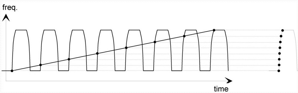
The 13 digits/s on a data sheet does not mean every measurement returns 13 digits. It means 13 significant digits are available at a gate time of 1 second. A modern counter works by reciprocal counting with interpolation, or time stamping: during the gate it records how many signal periods passed and the instants at which counting started and stopped, then divides the period count by the elapsed time to obtain frequency. A longer gate accumulates more periods, so the timing error of the start and stop instants becomes a smaller fraction of the total and the digit count rises; shorten the gate to 10 ms and you lose roughly two digits. The CNT-104R gate time is adjustable from 50 ns all the way to 1000 s exactly so that the user can trade measurement speed against measurement detail.
Compare models at the same gate time. The CNT-104S and CNT-102 are specified at up to 13 digits/s; the CNT-91/91R, CNT-90 and CNT-90XL at 12 digits/s (the CNT-90XL figure is stated for a 1 second measurement time). Displayed digits are a separate matter: the CNT-91 and CNT-90XL can show up to 14 digits, but that is the capability of the display, not the measurement resolution.
The second number is single-shot time resolution, the granularity of an individual time stamp: better than 7 ps on the CNT-104S and CNT-104R, 14 ps on the CNT-102, 35 ps on the CNT-91/91R, 70 ps on the CNT-90 and 100 ps on the CNT-90XL. It sets the rate at which frequency resolution improves with gate time, and more importantly it is the floor for single-event measurements such as time interval, pulse width and rise time. A start-to-stop interval happens once, there is no gate to lengthen, and the only remedy is to average repeated events. If your work is mainly time interval and jitter, look at this number before digits per second.
Channel count and gapless parallel acquisition
A traditional counter has A and B inputs but performs one measurement at a time: measure, process the result, start the next, with dead time in between. The CNT-90, CNT-91/91R and CNT-90XL are the fast version of that architecture, storing up to 250,000 results per second in internal memory (3.5M results on the CNT-91, 750k on the CNT-90), which is more than enough for frequency, period or time interval statistics on a single signal.
The CNT-104S and CNT-102 use a different architecture: every channel time stamps every trigger edge in parallel, continuously and without gaps. The CNT-104S has 4 parallel inputs (to 400 MHz) with a 50 ns sampling interval per channel and a total measurement rate of 20 million per second; the CNT-102 has 2 channels at 1 million per second. Block mode reaches 170,000 per second on both. Because all channels share one time base and one time axis, phase, time difference and simultaneity between channels hold by construction and need no alignment afterwards.
When do you need parallel channels? Whenever you have to establish that two things did or did not happen at the same moment: production test of several oscillators at once, tracking phase drift between two clocks, skew across the outputs of a distribution amplifier, or time-of-flight with one start and several stops (the CNT-104S supports 1 start and 3 stops). If your present method is one counter per signal plus some way of lining up the time axes afterwards, a multichannel instrument is what replaces it. Where the work is a single signal, the CNT-9x architecture is entirely sufficient, and its interfaces (USB, GPIB) fit existing ATE programs more easily.
Microwave inputs and pulsed RF
The standard channel to 400 MHz covers most clock and reference signals. Above that you need the optional microwave channel: 3, 8, 15 or 20 GHz on the CNT-91/91R; 3, 8, 15 or 20 GHz on the CNT-90; up to 24 GHz on the CNT-102 (3 / 10 / 15 / 20 / 24 GHz); and on the CNT-104S a Channel C whose base hardware is 3 GHz or 10 GHz, where the 10 GHz version can be upgraded in software to 15 / 20 / 24 GHz, which is useful when the budget says buy the basic unit now and upgrade later.
Above 24 GHz, or for pulsed RF, the CNT-90XL takes over. Its input C covers 0.3 to 27, 40, 46 or 60 GHz depending on model, with -33 dBm sensitivity from 0.3 to 18 GHz, and it measures power at the same time (-35 dBm to +10 dBm; typical accuracy better than 1 dBm to 27 GHz). Option 28 adds pulsed RF measurement: pulse widths from 30 ns to 1 second at 200 ps rms resolution, so carrier frequency inside the pulse, pulse width and pulse repetition interval on a radar or communication module are read directly, with no demodulation step.
Two points to watch when selecting. The microwave channel is usually a single channel, the CNT-104S being the exception since it runs alongside the four 400 MHz channels. And frequency resolution in a microwave measurement is still governed by the time base and the gate time: a high carrier does not degrade relative resolution, but absolute frequency error in Hz scales with the carrier, which makes time base quality matter more, not less.
Time base: TCXO, OCXO, rubidium clock or an external 10 MHz
A counter is never more accurate than its time base. However long the gate and however many digits are shown, if the time base itself is off by 1×10⁻⁷ then a 10 MHz signal reads 1 Hz away from the truth. The time base is the item most often underestimated during selection, and the one with the largest effect on measurement uncertainty.
The usual grades, lowest to highest: TCXO (temperature compensated crystal, standard on the CNT-102, 1 ppm/year); OCXO (oven controlled crystal, offered on the CNT-91 and CNT-90 at 0.01 ppm/month or 0.003 ppm/month, with options 30/90 and 40/90 on the CNT-90XL covering the same two grades, a TCXO and two OCXO grades on the CNT-104S, and two accuracy grades of OCXO on the CNT-102); and a built-in rubidium oscillator (CNT-91R, and the CNT-104R with its internal 10 MHz rubidium clock, frequency calibration accuracy better than 1×10⁻¹¹, reaching 1×10⁻¹² on a 24 hour average with the optional GNSS module).
The decision is straightforward. If the laboratory already has a traceable 10 MHz reference, for example a signal distributed from an FTR-210R or a 6688/6689, connect it to the external reference input of the counter; the grade of the internal time base then matters much less and an OCXO will do. If the counter travels, goes into a vehicle or to a customer site, or is itself the most accurate thing in the laboratory, choose the R version with the built-in rubidium clock. For reference and distribution planning see "Laboratory Time and Frequency References: GNSS-disciplined Rubidium and Standalone Sources" Laboratory Time and Frequency References: GNSS-disciplined Rubidium and Standalone Sources.
Measurement speed, memory and analysis software
Statistics and jitter analysis feed on sample count, so measurement rate and memory depth decide directly whether you can see an intermittent event at all. The CNT-9x family runs at 250,000 measurements per second with 750k (CNT-90) to 3.5M (CNT-91) results of memory; the CNT-104S runs at 20 million per second, and the CNT-104R holds up to 32M samples internally. Streaming live to a PC over GPIB is limited by the bus (up to 4,000 results/s on the CNT-91, 2,000 per second on the CNT-90), which is why high-speed capture always writes to internal memory first and reads out in a block. The CNT-104S and CNT-102 include Gbit Ethernet and a built-in web server as standard, so integrating them into an automated test system needs no extra interface card.
The CNT-9x family is primarily a numeric display. To see how frequency changes over time you need TimeView software: free-running sampling up to 250 kSa/s, repetitive sampling at an equivalent rate up to 100 MSa/s (minimum delay 10 ns), time stamp resolution of 35 ps rms (CNT-91/91R) or 70 ps rms (CNT-90/90XL), turning 1.9M (CNT-91/91R) or 375k (CNT-90/90XL) results into frequency/time, phase/time, histogram and FFT plots. Check the version when ordering: TimeView 2 (Option 29/90) supports the CNT-90, CNT-90XL, CNT-91 and CNT-91R, while TimeView 3 (Option 29/91) supports only the CNT-91/91R.
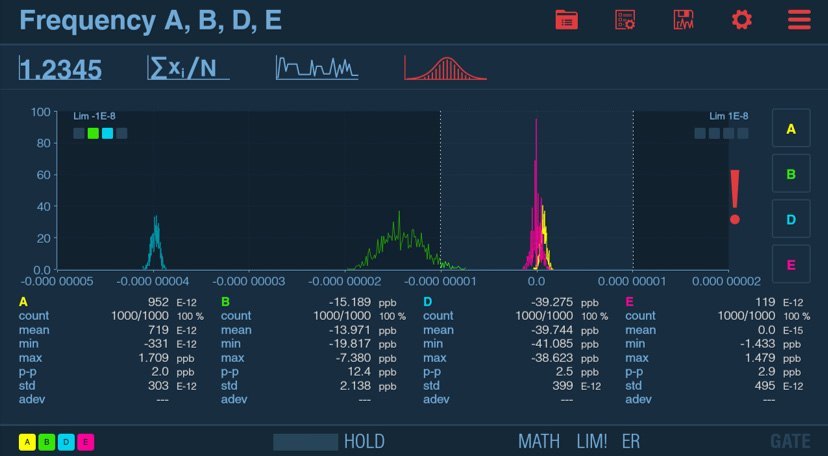
The CNT-104S and CNT-102 instead build modulation domain analysis into a large color touch screen, showing graph and numbers together. FM, FSK, BPSK, PWM and PPM modulation can be observed directly with no additional software. That is one of the differences between the two architectures in total cost of ownership.
A decision path by application
Production test of oscillators and clock modules: throughput and channel-to-channel consistency decide it. The four parallel channels of the CNT-104S test four DUTs at the same time, and the rack option (option 22/05) fits 8 units into 2U of a 19 inch rack, 32 channels in parallel under central control over Gbit Ethernet. Where a station needs only 2 channels, the CNT-102 gives the same 13 digits/s and 14 ps more economically.
Calibration laboratory: traceability and uncertainty decide it. The CNT-104R has a built-in 10 MHz rubidium clock with frequency calibration accuracy better than 1×10⁻¹¹, and with the optional GNSS module a time calibration uncertainty better than 10 ns rms to UTC, so one instrument compares four units under calibration at once. The traditional route is the CNT-91R (built-in rubidium clock, 35 ps, 12 digits/s, GPIB). Whichever you choose, connect it to the 10 MHz reference of the laboratory.
Radar, communication modules and microwave components: you need carrier frequency, power and pulse parameters, so choose the CNT-90XL in the 27, 40, 46 or 60 GHz version and add option 28 for pulsed RF. If the carrier is below 24 GHz and you also have to watch baseband clocks, a CNT-104S with Channel C is capable of the job.
R&D bench on a limited budget: the CNT-102 offers the flagship 13 digits/s and gapless 2 channel acquisition with graphical analysis built in. Where compatibility with existing GPIB programs is required, or the work has to run away from mains power, the CNT-90 (90 Wh battery option, over 4.5 hours) remains the practical choice. Three reminders apply to all of them: check whether your highest input frequency exceeds 400 MHz, check whether the laboratory has an external 10 MHz reference, and where the work is mainly time interval, put single-shot resolution ahead of digits per second.